3D models play a critical role in most manufacturing processes.
Customers use 3D models to visualize a product before it becomes tangible and engineer load calculations to prove a product will meet specific design criteria—to name a couple of common use cases.
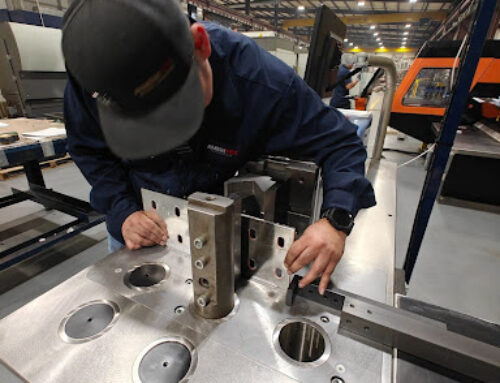
Sheet metal fabricators rely on 3D models for different but equally important reasons. A big one is programming machines to create customers’ parts as quickly and accurately as possible.
For this reason, we encourage all customers to provide manufacturable models when requesting metal fabrication services.
What Is a Manufacturable Model?
In the simplest terms, a manufacturable model is a 3D model that your manufacturer can use as is (i.e., without modifications) to program their machines.
Unfortunately, it’s still common to see 3D models intended for visual representation or reference only. These models cannot be used directly for manufacturing, meaning if you paid a designer to create it for you, you’d need to pay them to create another one that’s actually manufacturable.
No one should have to pay for multiple 3D models of the same custom fabrication. So before going through the (important and valuable!) work of creating a 3D model, you want to ensure you get what you need the first time.
Quick Tips for Developing Manufacturable Models for Metal Fabrication Services
If you’re paying for 3D modeling services and intend to seek metal fabrication services, pay for the model once by ensuring that it checks these boxes:
- Real material thicknesses. When possible, always model sheet metal parts using gauge charts—which are readily available online. If you’re working with a foreign design firm but plan to have your custom fabrication manufactured in the United States, make sure they do not use all metric materials.
- Accurate hole sizes. The hole sizes specified in the 3D model should be the sizes that need to be cut into the part. Have the designer size the holes with clearance for hardware and coatings.
- Achievable bend radius. It’s important to model bends in sheet metal with an achievable bend radius, so instruct your designer to avoid 90-degree corners. Parts should be modeled with a bend radius that is as tight as possible without sacrificing the integrity of the part, having an extra large bend radius requires oversized tools which limits the complexity of the part.
- Correct modeling tools. If a custom fabrication is structural or sheet metal, the designer should use the structural and sheet metal tools in the modeling platform to ensure shapes and geometries are accurate to real-world requirements. These tools will make sure that, at a high level, the geometries modeled follow the general rules of sheet metal and structural design.
In addition to following these best practices, feel free to share some of our Design for Manufacturing tips with your designer so that your part design is optimized for quick and cost-effective manufacturing: