When you need a high-quality sheet metal part turned around quickly and cost-effectively, it helps to make your precision sheet metal fabrication partner’s job as easy as possible.
Don’t get us wrong—a great shop will always work with you to get you exactly what you want. But if there are things you can do to speed a project along and have top-notch parts in your hands ASAP, wouldn’t you like to know what they are?
Today, we’re sharing our industry secrets for designing sheet metal parts any shop can make in their sleep.
8 Tips for Designing Precision Sheet Metal Parts
1. Design flanges long enough for the particular material thickness
When a part requires sheet metal bending, it’s critical to have enough material to reach across the press brake’s v-shaped die, which is typically set to 5-8 times the material thickness.
The die ultimately determines how short the flanges can be. A best practice is to multiply your material thickness by 8 and design flanges to be about half of that measurement to ensure the material reaches the other side.
2. Avoid designing features too close to bends
The v-die also determines where features should be designed in a custom fabrication. If features are too close to the area being bent, they can become stretched or deformed during the bending process.
To avoid this outcome, we recommend placing features outside the die by a considerable amount—1.5x the thickness of the material plus the inside radius of the bend, to be exact. This calculation usually equates to 3-4x the thickness of the material when using 5-8x material thickness for the die size. However, it will increase as the bend radius and die sizes increase.
3. Use readily available materials
Check with your precision sheet metal fabrication partner to see which materials they currently have in stock. If you have some flexibility regarding the material you use, stick with one that’s readily available to eliminate any sourcing challenges and get your part faster.
At Ameritex, we have 304 stainless steel, 316 stainless steel, 5052 aluminum, 6061 aluminum, A36 steel, 1008 carbon steel, and Grade 50 carbon steel in stock on a daily basis.
4. Draw your model as sheet metal
When designing a sheet metal part, all features must be the same thickness since they come from a single piece of sheet metal.
Drawing your model as sheet metal in the CAD software will ensure uniform thickness and bend reliefs as required to prevent the metal from deforming at the bend lines.
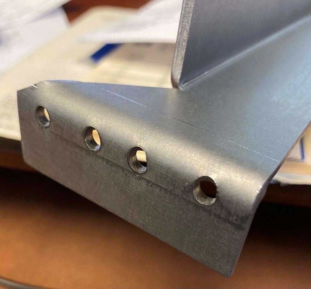
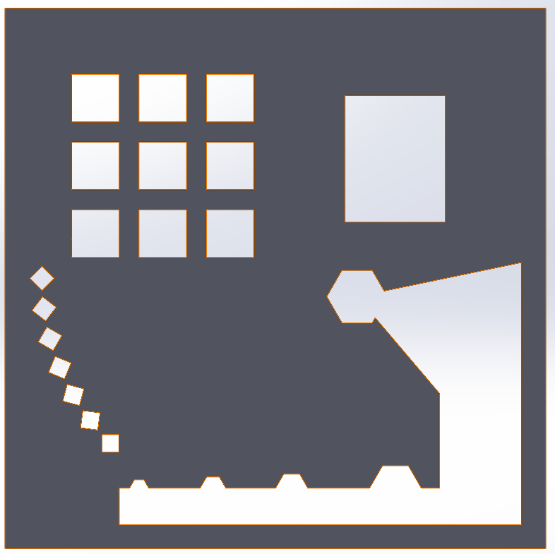
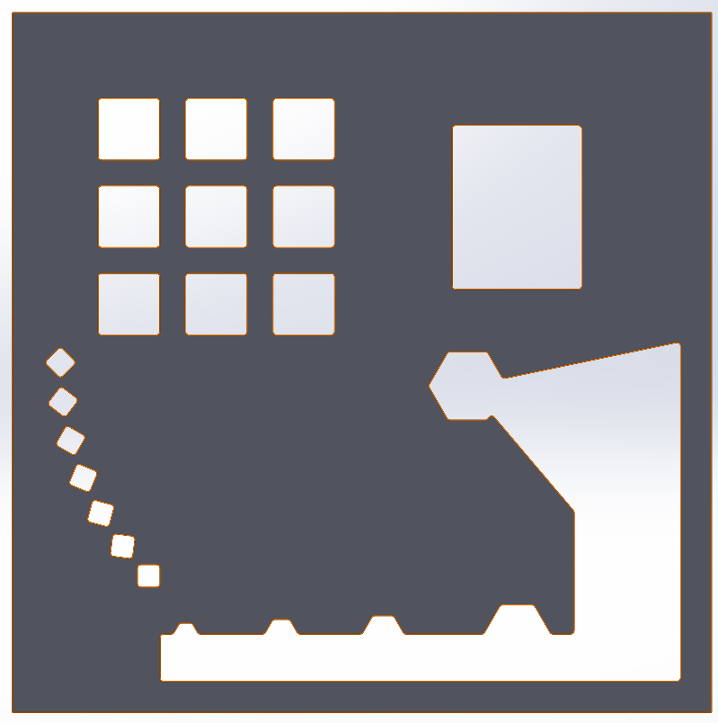
5. Radius sharp corners
Whenever possible, place a small radius on sharp points to get a cleaner-looking part. This minor change ensures a smoother laser cutting process by allowing the laser to change directions quickly and easily.
In most cases, these tiny visual alterations can be made small enough to be nearly undetectable on the final product.
Below you will find common cut features drawn with square corners, then the same features with radius corners to allow for smoother cutting on the laser and a more professional looking end product.
6. Be flexible about your bend radius
If a particular bend radius is critical to the functionality of your custom fabrication, your precision sheet metal fabrication partner may need to invest in custom tools to achieve the specific punch and die combination.
On the other hand, if you have some flexibility regarding your bend radius, they’ll be able to get to work right away using the standard tools they already have.
7. Provide a drawing in addition to a model
Models are important, but they aren’t sufficient on their own. Precision sheet metal fabrication shops also need drawings with notes detailing hardware installation, tapped holes, counterbore depth, CNC machining needs, and other specifications.
An annotated drawing serves as our go-to guide for building a custom fabrication accurately.
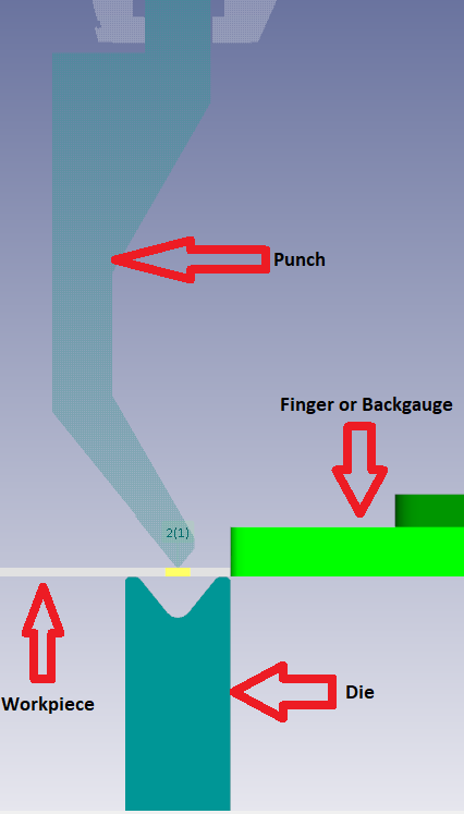
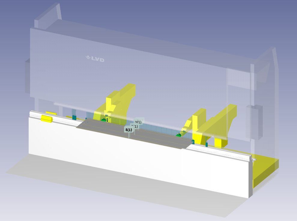
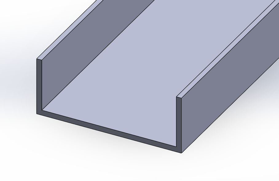
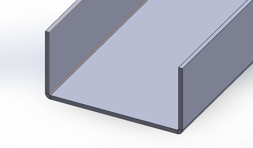
8. Leave room for tooling to bend the part
Familiarize yourself with how a punch and die interact with a piece of sheet metal, and be sure to leave room for the tooling to bend your part.
Designing two bends too close together or multiple bends in various directions could result in tool collision.
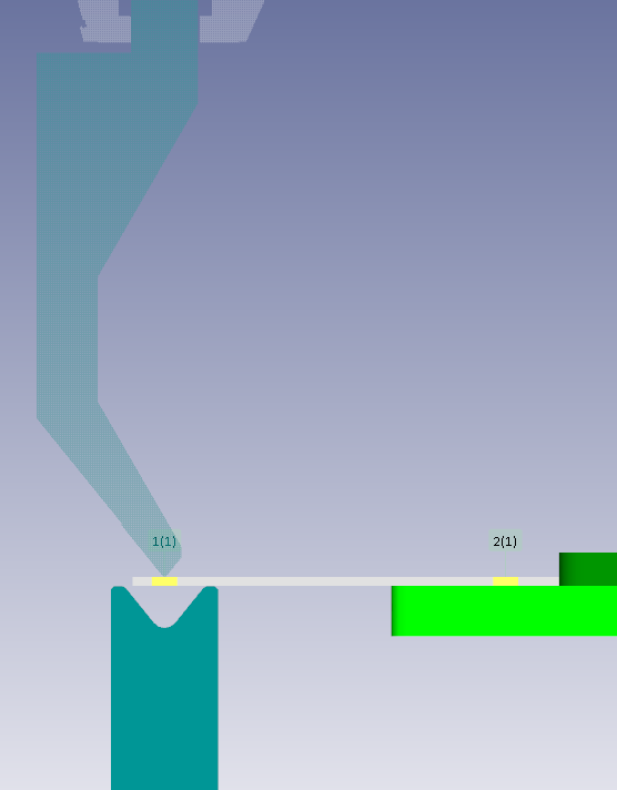
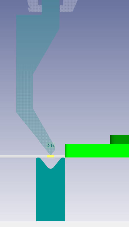
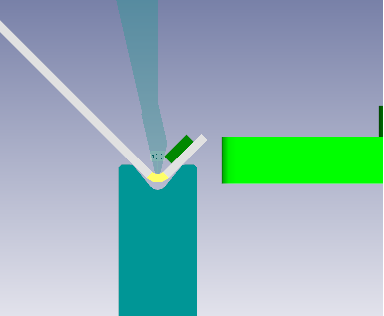
Positioning hardware relative to the bend is also a critical feature, below you can see why there are limitations in how close the hardware can be in order to bend a part with hardware installed. If the hole that the hardware installs gets stretched due to being too close to the bend, there may be a failure in the hardware.
Understanding punch and die basics will get you far, but if you have questions about the dimensions, limitations, and capabilities of specific tooling, don’t hesitate to ask your precision sheet metal fabrication partner.
Hopefully, these tips will help you have a smoother experience next time you need metal fabrication services. When that time comes, we encourage you to reach out to us—we promise you won’t be disappointed!