We talk a lot on this blog about how to optimize sheet metal fabrication designs to improve quality, cost, and lead time.
But perhaps the easiest way to guarantee all three of these benefits is to let the experts at Ameritex design your sheet metal part or assembly for you.
We’re proud to offer comprehensive design and engineering services to our valued customers. Read on to learn more about what to expect from this process.
Why Choose Ameritex for Sheet Metal Design and Engineering Services?
All too often, there’s a disconnect between what works well in a 3D CAD model and what’s actually manufacturable on the shop floor. Engineers may think they’re designing a sheet metal part that’s easy to fabricate, but unfortunately that’s not always the case.
When a precision sheet metal fabrication shop receives a model that hasn’t been optimized for factors like tooling, material thickness, and hardware installation (just to name a few examples), the shop will take one of two actions: 1) fabricate the part to spec, even if it means charging the customer more money than necessary or 2) send the design back to the customer with recommended changes, which inevitably increases lead time.
At Ameritex, we want our customers to avoid both of these scenarios whenever possible.
By incorporating our sheet metal expertise into a design from the very beginning, we provide customers with a set of prints they can take anywhere to have their part made quickly and cost-effectively—though most customers stick with us for metal fabrication services as well.
Curious how the design and engineering process works? We’re happy to outline it for you!
Ameritex’s Sheet Metal Design and Engineering Process
- Step 1: Design intent. The first step in the process is determining the design intent. We assess the function of the part or assembly, and document basic specifications like overall dimensions and material type. Lead Time: (Scheduled 3-5 days from the receipt of order)
- Step 2: Initial design. Once we understand the functionality of the part or assembly, we create a conceptual 3D CAD model that includes standard features such as part thickness, flange locations, and welding requirements. We send this initial design to the customer for feedback. Lead Time: (Typically 1-3 weeks depending on part or assembly complexity)
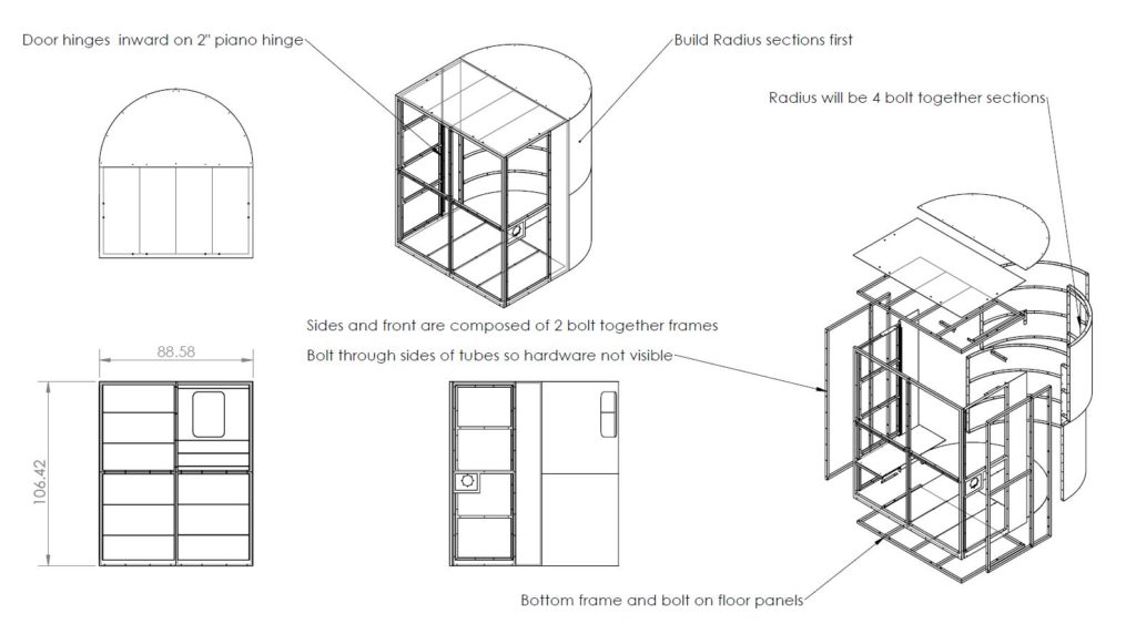
- Step 3: Functional model. During this step in the process, we incorporate any detailed components the customer may have provided in their design review (e.g. valves, pumps, push buttons, electrical components, latches, drawer slides, eyelets). We then create and present a functional 3D CAD model. Customers have the ability to view the entire part in precise detail before giving final approval. Lead Time: (Typically 1-3 weeks after initial design is approved)
- Step 4: Fabrication print. After receiving final approval on the design, we make a fabrication print (i.e. a 2D PDF file) and send it to customers to keep in their records. From that point, customers can send the print to any precision sheet metal fabrication shop—or, for the most seamless process, they can have Ameritex make their part or assembly. We recommend the second option. 😉 Lead Time: 3-5 days after functional model is approved
The best thing about our sheet metal design and engineering process is that we can jump in at any point. Starting from scratch? We’ll walk you through the entire 4-step process. Already have a 3D CAD model? Great, send it to us for a free 15-minute design review and to determine next steps.
When you’re ready for design and engineering services, we’re here to serve you. Request a quote and let’s get started!